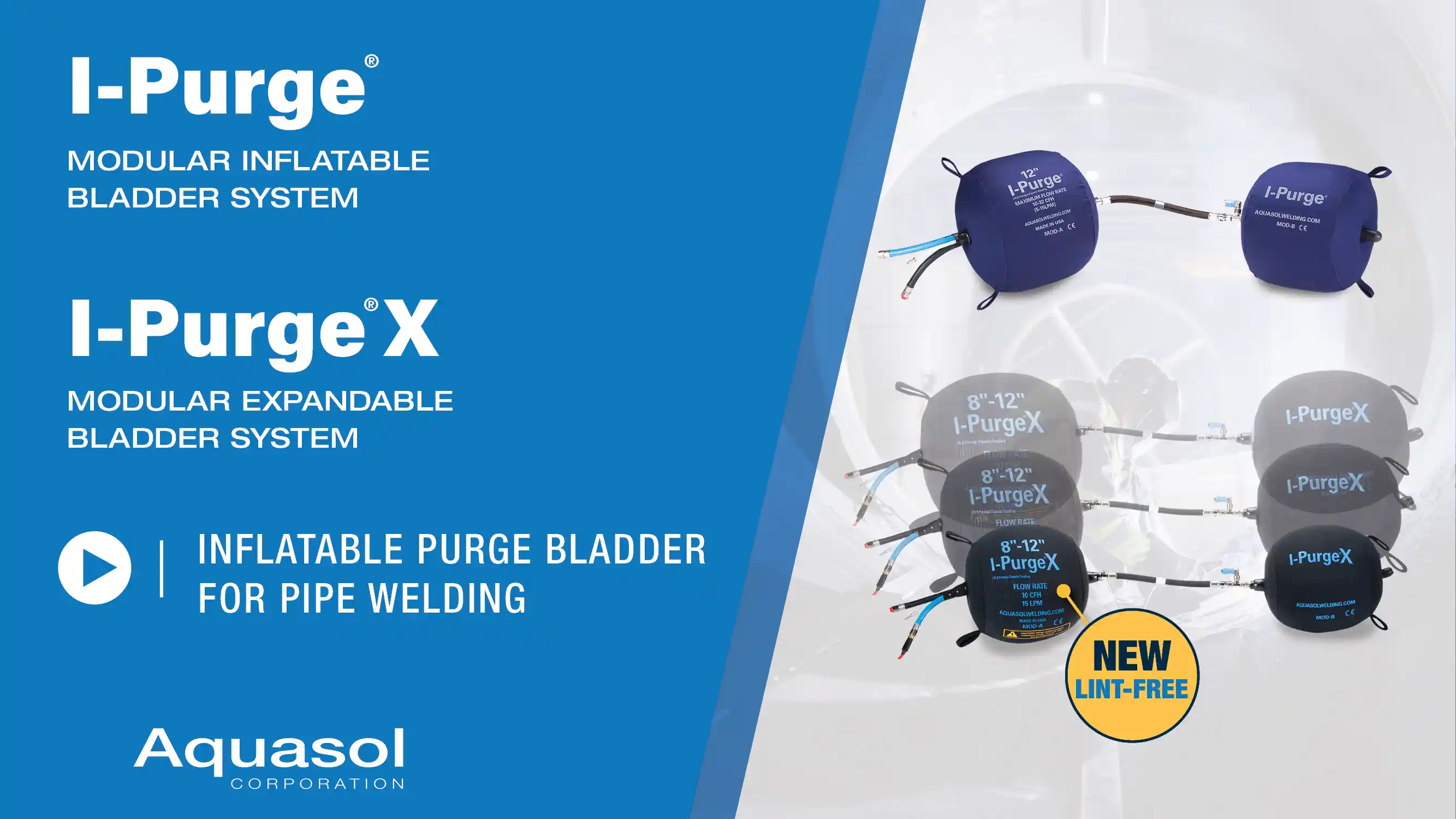
®
SISTEMA MODULAR DE BOLSA INFLABLE
PATENTES CONCEDIDAS EN EE. UU. Y EN EL EXTRANJERO |
FABRICADO EN EE. UU.
La solución más versátil y adaptable para la purga de tuberías: ofrece un rendimiento rápido y eficiente con un consumo mínimo de gas y la máxima calidad de soldadura.
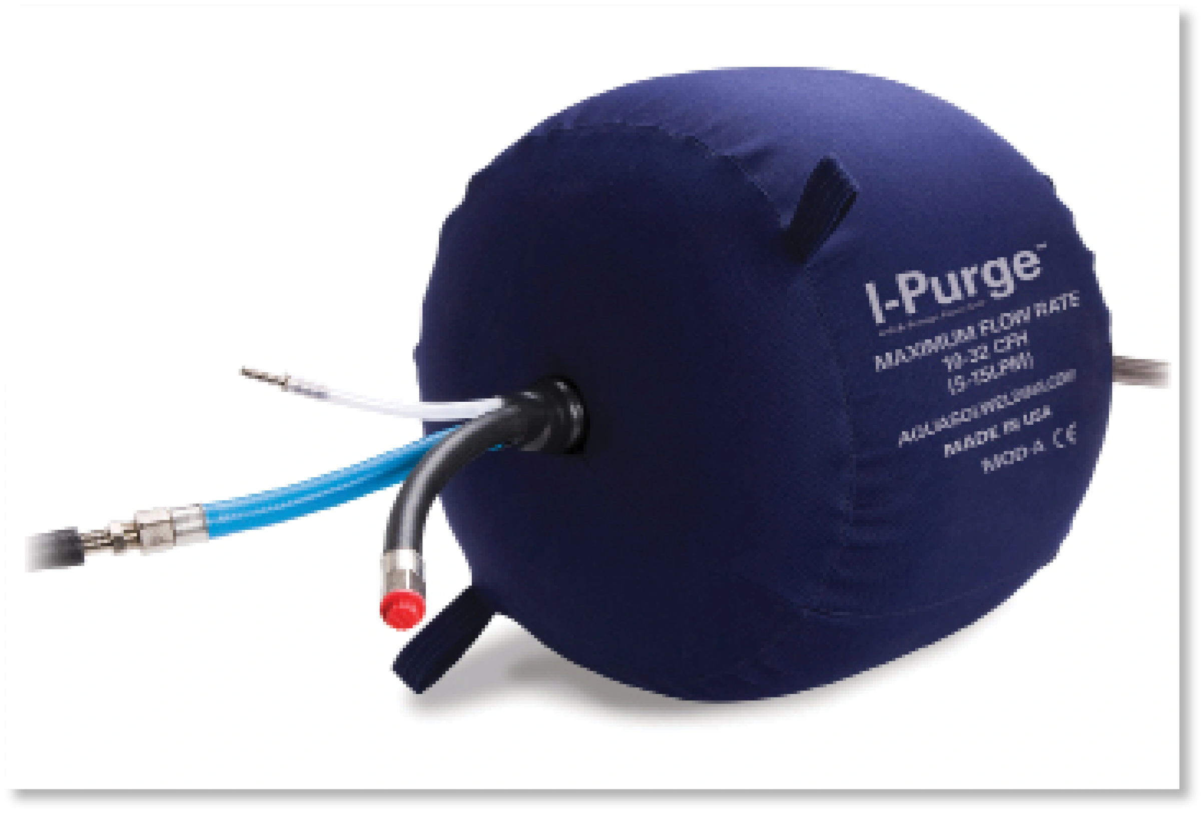
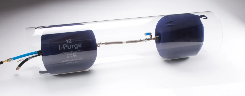
El revolucionario Sistema Modular de Vejigas Inflables I-Purge®, con patente en trámite, es el sistema de purga de cañerías más innovador y versátil que existe. I-Purge forma un sello impermeable para consumir la menor cantidad de gas de purga durante el purgado y la soldadura del caño, ahorrando tiempo y dinero, y lograr soldaduras uniformes de alta calidad.
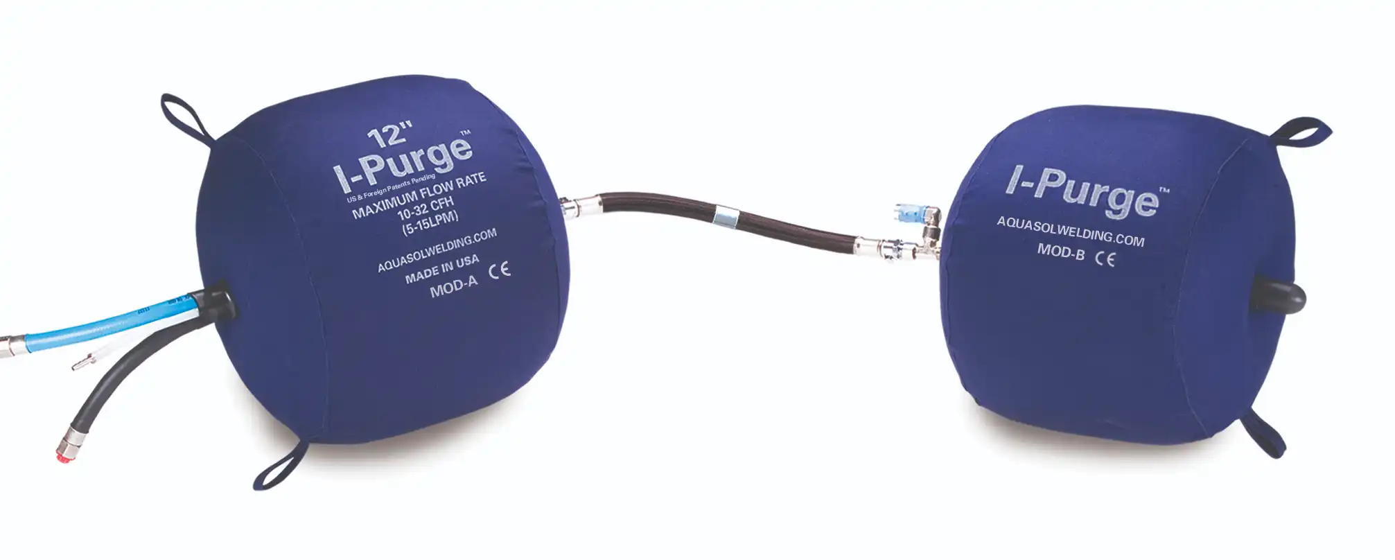
Fabricado en los EE. UU., este sistema de vejigas reutilizables de larga duración permite a los operadores satisfacer una variedad de necesidades de purgado con una única solución intercambiable. El I-Purge viene equipado con diversos dispositivos muy avanzados como sus Accesorios de Conexión Rápida que encajan a la perfección y facilitan el montaje y desmontaje de los componentes. El I-Purge también viene con un arnés termorresistente de gran longitud que permite colocar las vejigas fuera de la zona afectada por el calor y también puede admitir aplicaciones de precalentamiento o alto calor.
Estas funciones de avanzada permiten al operador crear múltiples configuraciones como las de un obturador de cañería unilateral y un reductor.Las vejigas vienen en tamaños de 2 a 48″ (51- 1219 mm) y pueden comprarse ya sea por separado o como un sistema completo, algo que representa una importante ventaja en caso de desear otros tamaños o de necesitar reemplazar algún componente.
Ideal para talleres de fabricación, el I-Purge supera la tecnología actual con su avanzado diseño y brinda la solución completa para todas las necesidades de purga de cañerías.
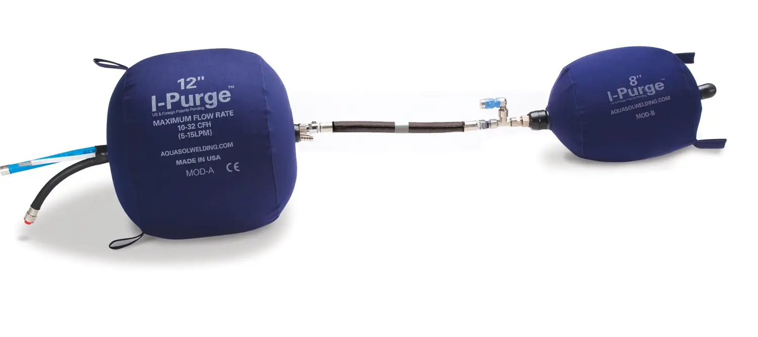
Vejigas Inflables Módulos A y B
Arneses Largos Termorresistentes
Accesorios Intercambiables de Conexión Rápida
Válvula de Alivio Exclusiva
Difusor de Gas Inerte
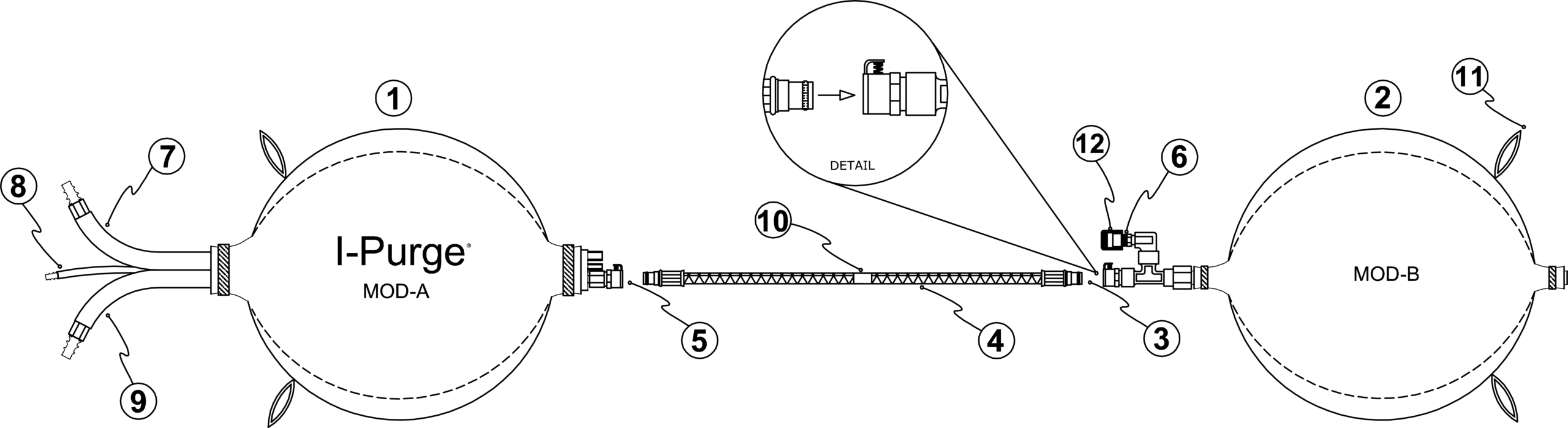
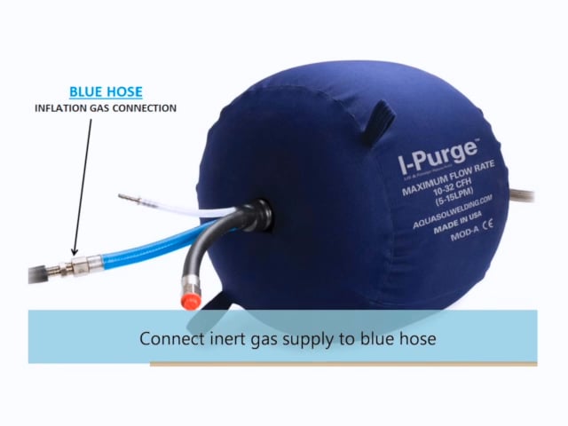
Sistema de Tuberías Internas Tri-Flow (Mangueras Azul, Negra y Blanca)
Múltiples puertos de entrada/escape para un purgado más rápido y más eficiente de la soldadura
Conexiones Separadas:
Azul – Inflado de Vejigas La primera función es inflar las vejigas y luego inundar la zona de la soldadura con gas noble
Negra – Aumentar la Inundación de la Zona de la Soldadura
Diseñada para agilizar el purgado, la manguera de purga (NEGRA) secundaria se usa para inundar el área de soldadura con gas inerte y evacuar el oxígeno a mayor velocidad, para entonces poder iniciar la soldadura
Blanca – Conexión de Escape
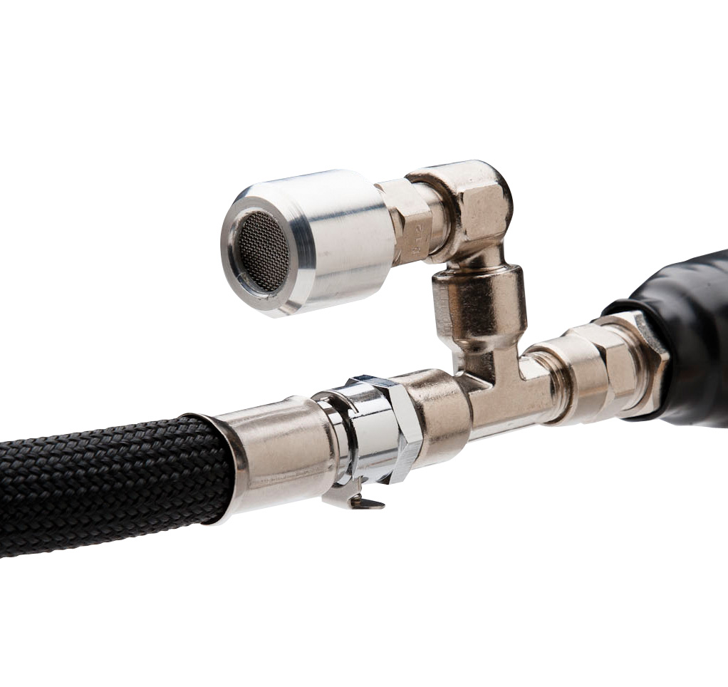
Conecte esta manguera a un Monitor de Oxígeno, como el Pro Ox-100 de Aquasol que obtiene lecturas de hasta 100 PPM (0,01%), para un monitoreo continuo o puntual del oxígeno en la zona de la soldadura
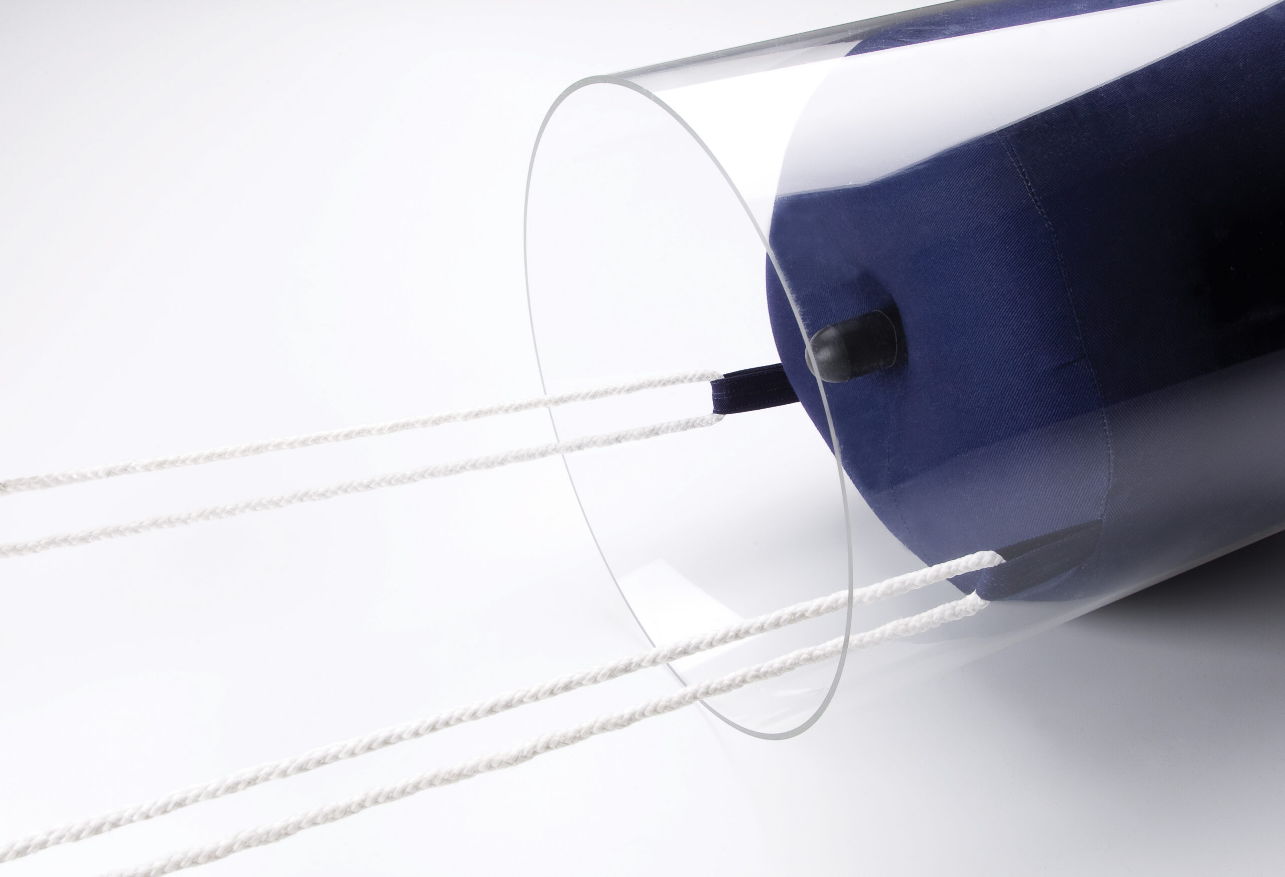
Argollas de Tiro
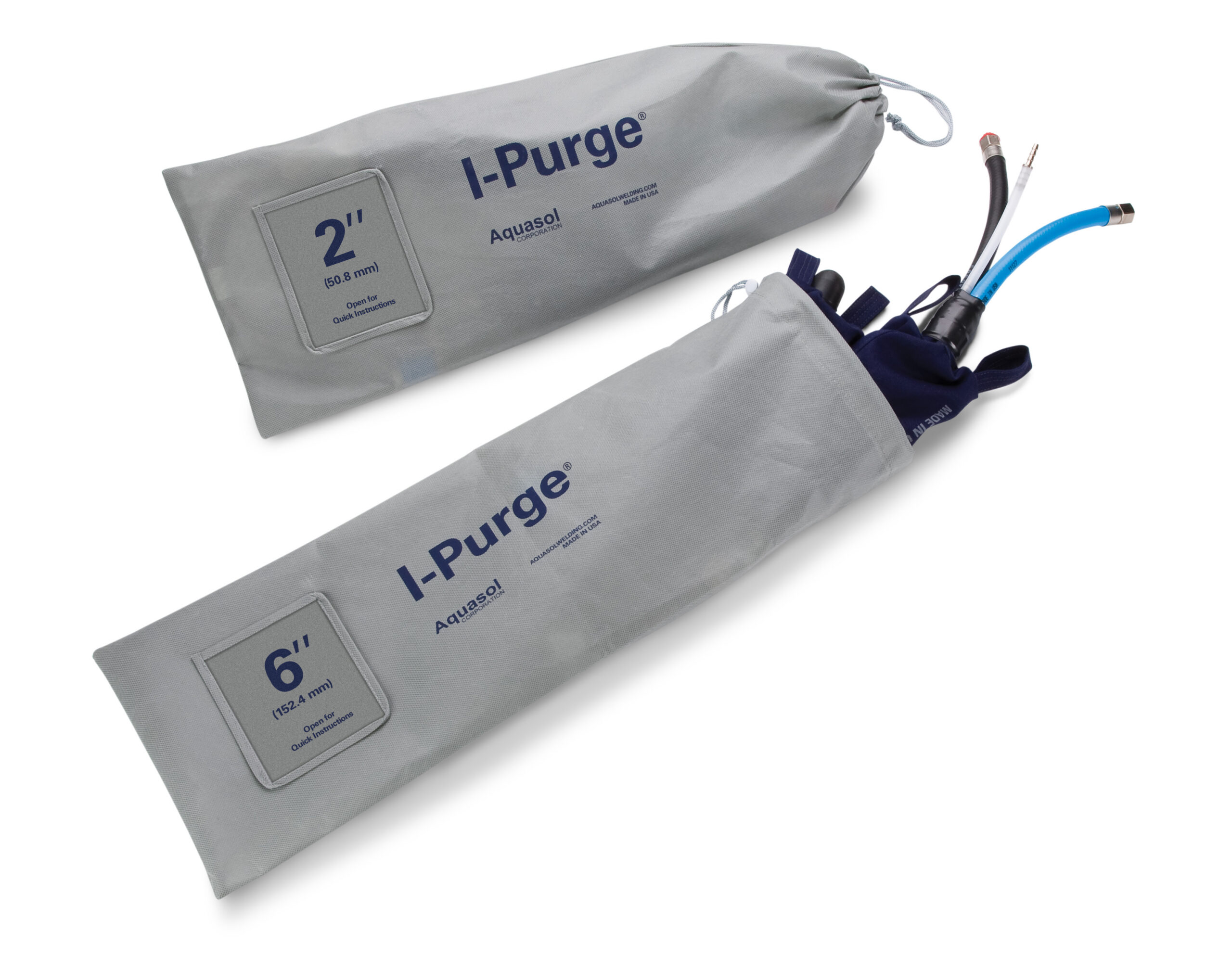
Bolsa de Guarda
Reductor I-Purge
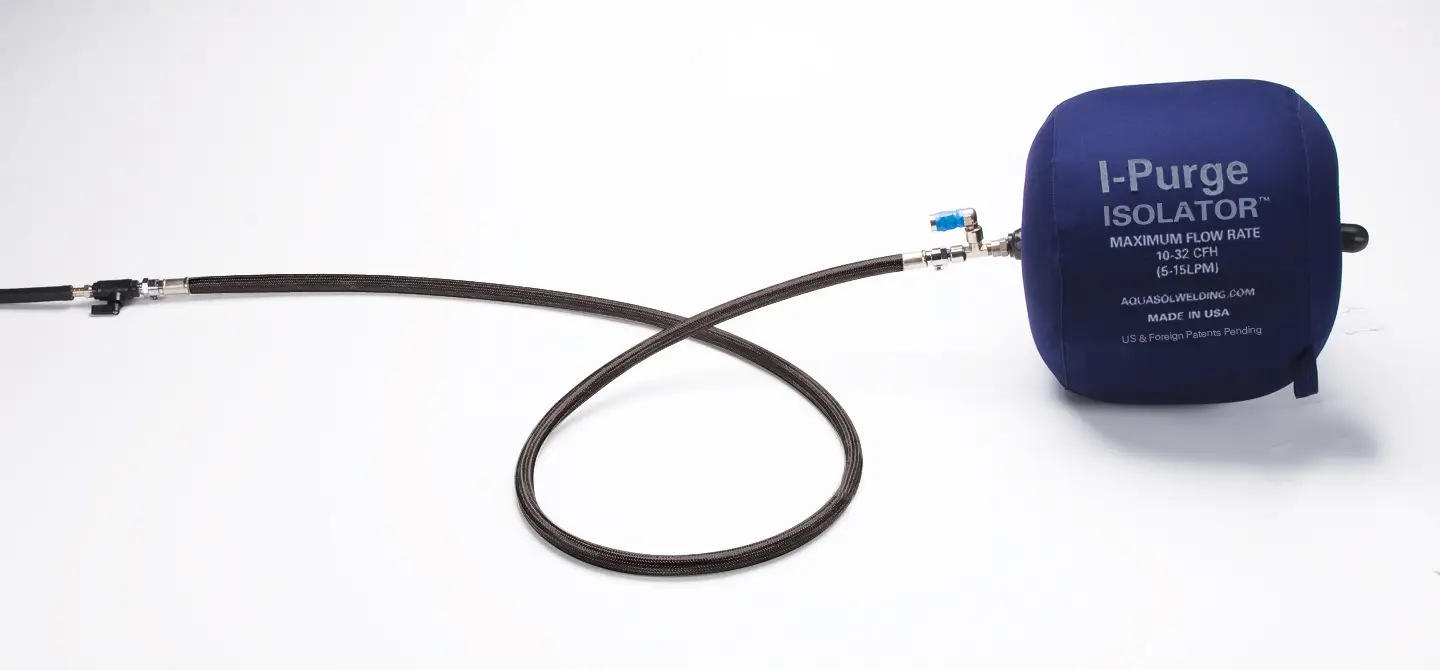
Obturador Inflable de Caño y Vejiga Simple de Purga I-Purge Isolator
Adaptadores de aislamiento I-Purge:
¡Aproveche al máximo nuestro diseño modular!
Convierta sus sistemas I-Purge de dos bolsas en aisladores de un solo lado para geometrías de soldadura complejas. Tanto nuestras bolsas I-Purge como I-Purge X pueden convertirse gracias a nuestro innovador diseño modular.
Adaptador I-Purge Mod-A: Un difusor de conexión rápida para su bolsa I-Purge Mod-A.
Adaptador I-Purge Mod-B: Una manguera con accesorios de conexión para conectar su bolsa I-Purge Mod-B a su cilindro de argón.
Sistema Modular I-Purge:
Equipado con los Componentes Intercambiables Más Avanzados
Guía Rápida de Instrucciones
1. Verifique que I-Purge esté completamente ensamblado (esto es, que los módulos estén firmemente conectados al arnés mediante accesorios de conexión rápida).
2. Si fuera necesario, conecte soga, cadena o cable a las argollas de tiro en los extremos de los módulos de vejiga. Esto le permitirá insertar y extraer el sistema con facilidad.
3. Conecte las líneas de gas inerte a las mangueras AZUL y NEGRA. La manguera de gas AZUL se necesita para inflar las vejigas de purgado, en tanto que la manguera de gas NEGRA es opcional y sirve para agilizar el proceso de purgado
4. Posicione la unidad de purga en el caño alineando el indicador luminiscente con la separación de la raíz
5. Encienda el suministro de gas para inflar las vejigas y purgar la zona de la soldadura. Velocidades de Flujo Recomendadas para el Purgado: La manguera de gas AZUL debería transferir gas inerte a 10-32 SCFH (5-15 LPM) para los modelos 2″ – 34″ y 60 SCFH (28,5 LPM) para los modelos 36″ – 48″.
Caudales recomendados para el purgado:
La manguera de gas AZUL debe transferir gas inerte a 10-32 SCFH (15 LPM) para los modelos de 2″-34″, 60 SCFH (28,5 LPM) para los modelos de 36″-58″ y 120 SCFH (56,6 LPM) para los modelos de 60″-70″.
6. Una vez que ha logrado un sello estanco, comience a soldar.
7. Siempre mantenga una velocidad de flujo uniforme durante el inflado, purgado y soldadura.
8. Una vez concluida la soldadura, apague el suministro de gas para desinflar las vejigas. Cuando la zona de calor se haya enfriado lo suficiente, retire el I-Purge del caño. Asegúrese de desconectar todas las líneas de gas y equipos de monitoreo.
9. Limpie el I-Purge y guárdelo en la bolsa cuando no lo esté usando.
*(Consulte el Manual del Producto de Aquasol para obtener instrucciones detalladas)
| ITEM NO | DIMENSIONS | STANDARD HARNESS LENGTH | DESCRIPTION | ||
|---|---|---|---|---|---|
| English | Metric | English | Metric | ||
| ABLD 2 | 2″ | 51 mm | 11″ | 279 mm | 2″ I-Purge Double Purge Bag System with High Heat Harness |
| ABLD 3 | 3″ | 76 mm | 11″ | 279 mm | 3″ I-Purge Double Purge Bag System with High Heat Harness |
| ABLD 4 | 4″ | 102 mm | 11″ | 279 mm | 4″ I-Purge Double Purge Bag System with High Heat Harness |
| ABLD 5 | 5″ | 127 mm | 11″ | 279 mm | 5″ I-Purge Double Purge Bag System with High Heat Harness |
| ABLD 6 | 6″ | 152 mm | 11″ | 279 mm | 6″ I-Purge Double Purge Bag System with High Heat Harness |
| ABLD 8 | 8″ | 203 mm | 11″ | 279 mm | 8″ I-Purge Double Purge Bag System with High Heat Harness |
| ABLD 10 | 10″ | 254 mm | 12″ | 305 mm | 10″ I-Purge Double Purge Bag System with High Heat Harness |
| ABLD 12 | 12″ | 305 mm | 12″ | 305 mm | 12″ I-Purge Double Purge Bag System with High Heat Harness |
| ABLD 14 | 14″ | 356 mm | 16″ | 406 mm | 14″ I-Purge Double Purge Bag System with High Heat Harness |
| ABLD 16 | 16″ | 406 mm | 16″ | 406 mm | 16″ I-Purge Double Purge Bag System with High Heat Harness |
| ABLD 18 | 18″ | 457 mm | 16″ | 406 mm | 18″ I-Purge Double Purge Bag System with High Heat Harness |
| ABLD 20 | 20″ | 508 mm | 18″ | 457 mm | 20″ I-Purge Double Purge Bag System with High Heat Harness |
| ABLD 22 | 22″ | 559 mm | 18″ | 457 mm | 22″ I-Purge Double Purge Bag System with High Heat Harness |
| ABLD 24 | 24″ | 610 mm | 18″ | 457 mm | 24″ I-Purge Double Purge Bag System with High Heat Harness |
| ABLD 26 | 26″ | 660 mm | 20″ | 509 mm | 26″ I-Purge Double Purge Bag System with High Heat Harness |
| ABLD 28 | 28″ | 711 mm | 20″ | 509 mm | 28″ I-Purge Double Purge Bag System with High Heat Harness |
| ABLD 30 | 30″ | 762 mm | 20″ | 509 mm | 30″ I-Purge Double Purge Bag System with High Heat Harness |
| ABLD 32 | 32″ | 813 mm | 20″ | 509 mm | 32″ I-Purge Double Purge Bag System with High Heat Harness |
| ABLD 34 | 34″ | 864 mm | 20″ | 509 mm | 34″ I-Purge Double Purge Bag System with High Heat Harness |
| ABLD 36 | 36″ | 914 mm | 20″ | 509 mm | 36″ I-Purge Double Purge Bag System with High Heat Harness |
| ABLD 38 | 38″ | 965 mm | 36″ | 914 mm | 38″ I-Purge Double Purge Bag System with High Heat Harness |
| ABLD 40 | 40″ | 1016 mm | 36″ | 914 mm | 40″ I-Purge Double Purge Bag System with High Heat Harness |
| ABLD 42 | 42″ | 1066 mm | 36″ | 914 mm | 42″ I-Purge Double Purge Bag System with High Heat Harness |
| ABLD 44 | 44″ | 1117 mm | 36″ | 914 mm | 44″ I-Purge Double Purge Bag System with High Heat Harness |
| ABLD 46 | 46″ | 1168 mm | 42″ | 1067 mm | 46″ I-Purge Double Purge Bag System with High Heat Harness |
| ABLD 48 | 48″ | 1219 mm | 42″ | 1067 mm | 48″ I-Purge Double Purge Bag System with High Heat Harness |
| ABLD 50 | 50″ | 1270 mm | 42″ | 1067 mm | 50″ I-Purge Double Purge Bag System with High Heat Harness |
| ABLD 52 | 52″ | 1321 mm | 42″ | 1067 mm | 52″ I-Purge Double Purge Bag System with High Heat Harness |
| ABLD 54 | 54″ | 1372 mm | 42″ | 1067 mm | 54″ I-Purge Double Purge Bag System with High Heat Harness |
| ABLD 56 | 56″ | 1422 mm | 42″ | 1067 mm | 56″ I-Purge Double Purge Bag System with High Heat Harness |
| ABLD 58 | 58″ | 1473 mm | 42″ | 1067 mm | 58″ I-Purge Double Purge Bag System with High Heat Harness |
| ABLD 60 | 60″ | 1524 mm | 42″ | 1067 mm | 60″ I-Purge Double Purge Bag System with High Heat Harness |
| ABLD 62 | 62″ | 1575 mm | 42″ | 1067 mm | 62″ I-Purge Double Purge Bag System with High Heat Harness |
| ABLD 64 | 64″ | 1626 mm | 42″ | 1067 mm | 64″ I-Purge Double Purge Bag System with High Heat Harness |
| ABLD 66 | 66″ | 1676 mm | 42″ | 1067 mm | 66″ I-Purge Double Purge Bag System with High Heat Harness |
| ABLD 68 | 68″ | 1727 mm | 42″ | 1067 mm | 68″ I-Purge Double Purge Bag System with High Heat Harness |
| ABLD 70 | 70″ | 1778 mm | 42″ | 1067 mm | 70″ I-Purge Double Purge Bag System with High Heat Harness |
| ITEM NO | DIMENSIONS | DESCRIPTION | |
|---|---|---|---|
| English | Metric | ||
| ISO 2 | 2″ | 51 mm | 2″ I-Purge Isolator One-Sided Plug with 10' Hose and Valve |
| ISO 3 | 3″ | 76 mm | 3″ I-Purge Isolator One-Sided Plug with 10' Hose and Valve |
| ISO 4 | 4″ | 102 mm | 4″ I-Purge Isolator One-Sided Plug with 10' Hose and Valve |
| ISO 5 | 5″ | 127 mm | 5″ I-Purge Isolator One-Sided Plug with 10' Hose and Valve |
| ISO 6 | 6″ | 152 mm | 6″ I-Purge Isolator One-Sided Plug with 10' Hose and Valve |
| ISO 8 | 8″ | 203 mm | 8″ I-Purge Isolator One-Sided Plug with 10' Hose and Valve |
| ISO 10 | 10″ | 254 mm | 10″ I-Purge Isolator One-Sided Plug with 10' Hose and Valve |
| ISO 12 | 12″ | 305 mm | 12″ I-Purge Isolator One-Sided Plug with 10' Hose and Valve |
| ISO 14 | 14″ | 356 mm | 14″ I-Purge Isolator One-Sided Plug with 10' Hose and Valve |
| ISO 16 | 16″ | 406 mm | 16″ I-Purge Isolator One-Sided Plug with 10' Hose and Valve |
| ISO 18 | 18″ | 457 mm | 18″ I-Purge Isolator One-Sided Plug with 10' Hose and Valve |
| ISO 20 | 20″ | 508 mm | 20″ I-Purge Isolator One-Sided Plug with 10' Hose and Valve |
| ISO 22 | 22″ | 559 mm | 22″ I-Purge Isolator One-Sided Plug with 10' Hose and Valve |
| ISO 24 | 24″ | 610 mm | 24″ I-Purge Isolator One-Sided Plug with 10' Hose and Valve |
| ISO 26 | 26″ | 660 mm | 26″ I-Purge Isolator One-Sided Plug with 10' Hose and Valve |
| ISO 28 | 28″ | 711 mm | 28″ I-Purge Isolator One-Sided Plug with 10' Hose and Valve |
| ISO 30 | 30″ | 762 mm | 30″ I-Purge Isolator One-Sided Plug with 10' Hose and Valve |
| ISO 32 | 32″ | 813 mm | 32″ I-Purge Isolator One-Sided Plug with 10' Hose and Valve |
| ISO 34 | 34″ | 864 mm | 34″ I-Purge Isolator One-Sided Plug with 10' Hose and Valve |
| ISO 36 | 36″ | 914 mm | 36″ I-Purge Isolator One-Sided Plug with 10' Hose and Valve |
| ISO 38 | 38″ | 965 mm | 38″ I-Purge Isolator One-Sided Plug with 10' Hose and Valve |
| ISO 40 | 40″ | 1016 mm | 40″ I-Purge Isolator One-Sided Plug with 10' Hose and Valve |
| ISO 42 | 42″ | 1066 mm | 42″ I-Purge Isolator One-Sided Plug with 10' Hose and Valve |
| ISO 44 | 44″ | 1117 mm | 44″ I-Purge Isolator One-Sided Plug with 10' Hose and Valve |
| ISO 46 | 46″ | 1168 mm | 46″ I-Purge Isolator One-Sided Plug with 10' Hose and Valve |
| ISO 48 | 48″ | 1219 mm | 48″ I-Purge Isolator One-Sided Plug with 10' Hose and Valve |
| ISO 50 | 50″ | 1270 mm | 50″ I-Purge Isolator One-Sided Plug with 10' Hose and Valve |
| ISO 52 | 52″ | 1321 mm | 52″ I-Purge Isolator One-Sided Plug with 10' Hose and Valve |
| ISO 54 | 54″ | 1372 mm | 54″ I-Purge Isolator One-Sided Plug with 10' Hose and Valve |
| ISO 56 | 56″ | 1422 mm | 56″ I-Purge Isolator One-Sided Plug with 10' Hose and Valve |
| ISO 58 | 58″ | 1473 mm | 58″ I-Purge Isolator One-Sided Plug with 10' Hose and Valve |
| ISO 60 | 60″ | 1524 mm | 60″ I-Purge Isolator One-Sided Plug with 10' Hose and Valve |
| ISO 62 | 62″ | 1575 mm | 62″ I-Purge Isolator One-Sided Plug with 10' Hose and Valve |
| ISO 64 | 64″ | 1626 mm | 64″ I-Purge Isolator One-Sided Plug with 10' Hose and Valve |
| ISO 66 | 66″ | 1676 mm | 66″ I-Purge Isolator One-Sided Plug with 10' Hose and Valve |
| ISO 68 | 68″ | 1727 mm | 68″ I-Purge Isolator One-Sided Plug with 10' Hose and Valve |
| ISO 70 | 70″ | 1778 mm | 70″ I-Purge Isolator One-Sided Plug with 10' Hose and Valve |
| ITEM NO | DIMENSIONS | DESCRIPTION | |
|---|---|---|---|
| English | Metric | ||
| ABLD-ELH-24 | 24″ | 610 mm | 24″ (2′) Extended Length High Heat Harness |
| ABLD-ELH-36 | 36″ | 914 mm | 36″ (3′) Extended Length High Heat Harness |
| ABLD-ELH-48 | 48″ | 1219 mm | 48″ (4′) Extended Length High Heat Harness |
| ABLD-ELH-72 | 72″ | 1828 mm | 72″ (6′) Extended Length High Heat Harness |
| ABLD-ELH-CUSTOM | Any Size | Any Size | Custom Lengths Available Upon Request |
| ABLD-CNADP | NA | NA | 1/4″ Female MPT to 1/4″ Female BSPP Conversion |
I-Purge is designed to fit pipe schedules for each nominal pipe diameter from schedule 5 to schedule 160.
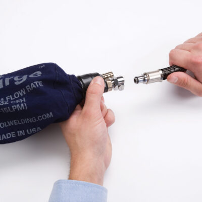
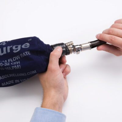
No tools are required when configuring the system. To assemble or disassemble the modules from the harness, simply press on the quick connect fitting at the end of each side of the harness and remove or connect.
The bridge harness is the connecting hose between the two inflatable bladders. It is comprised of a flexible braided fiberglass shielding over a high-heat resistant inner tube.
The central point of the bridge harness is marked with a luminescent indicator to easily align the center of the unit with the root gap. It is important to position the bladders at equal distances from the weld joint to prevent over heating of one side, which could rupture or damage the bladder.
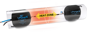
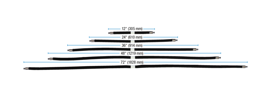
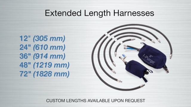
Extended length harnesses offer flexibility to extend placement of the inflatable bladders outside the heat affected zone (HAZ) and to accommodate pre-heating (high-heat) welding applications. Extended length harnesses are available in standard sizes including 12″ (305 mm), 24″ (610 mm), 36″ (914 mm), 48″ (1219 mm) and 72″ (1828 mm). I-Purge sizes 36″ and greater are equipped with a high flow harness to expedite inflation. Custom lengths are available upon request.
To prevent exposure to the HAZ, use an extended length harness appropriate for the situation. These harnesses are sold separately and are available in custom lengths.
I-Purge CAN be used in a pre-heated pipe. For pre-heating and high-heat applications, select an appropriate length of an extended harness to enable placement outside of the heat affected zone (HAZ).
The outer covering on the inflatable bags of I-Purge are the only component which should come into direct contact with the pipe. This material is infused with spark resistant elements which prevent it from catching fire when exposed to sparks and exceedingly hot objects. The outside material of the bladders can withstand temperatures as high as 400°F (205°C). Since the inside of the bladder has a lower heat resistance, it is advisable not to exceed a temperature of 250°F (120°C) for proper operation of the entire system.
I-Purge can accommodate higher temperatures by attaching an extended length harness purchased separately.
I-Purge offers the flexibility of combining modules of different sizes to create a unique configuration. For example, an 8″ (203 mm) module A can be connected to a 4″ (102 mm) module B.
The user MUST NEVER exceed the recommended expansion size labeled on the I-Purge. The unit will not function properly following an over inflation. Refer to manual for details.
If you believe the bladders were overinflated and burst during operation, terminate gas flow immediately. Overinflation can be prevented by adhering to the flow rates listed in the manual. Aquasol does not warrant any overinflation system failures. For more details, review Warranty and System Operation sections of the manual.
I-Purge X and I-Purge (standard) components CANNOT be interchanged. The calibration of the relief valve on I-Purge X is different from the standard I-Purge.
During some applications, the bladder component of the isolator may not be visible, therefore all I-Purge Isolator units are equipped with a pressure relief valve to prevent over inflation of the unit. Therefore, a constant supply of gas must be maintained to keep a tight seal on the pipe wall (Refer to Isolator – System Operation).