SISTEMA MODULAR DE BOLSA EXPANSÍVEL
PATENTES PENDENTES NOS EUA E NO EXTERIOR |
FABRICADO NOS EUA
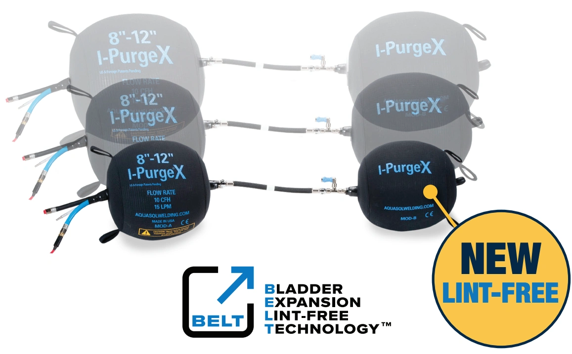
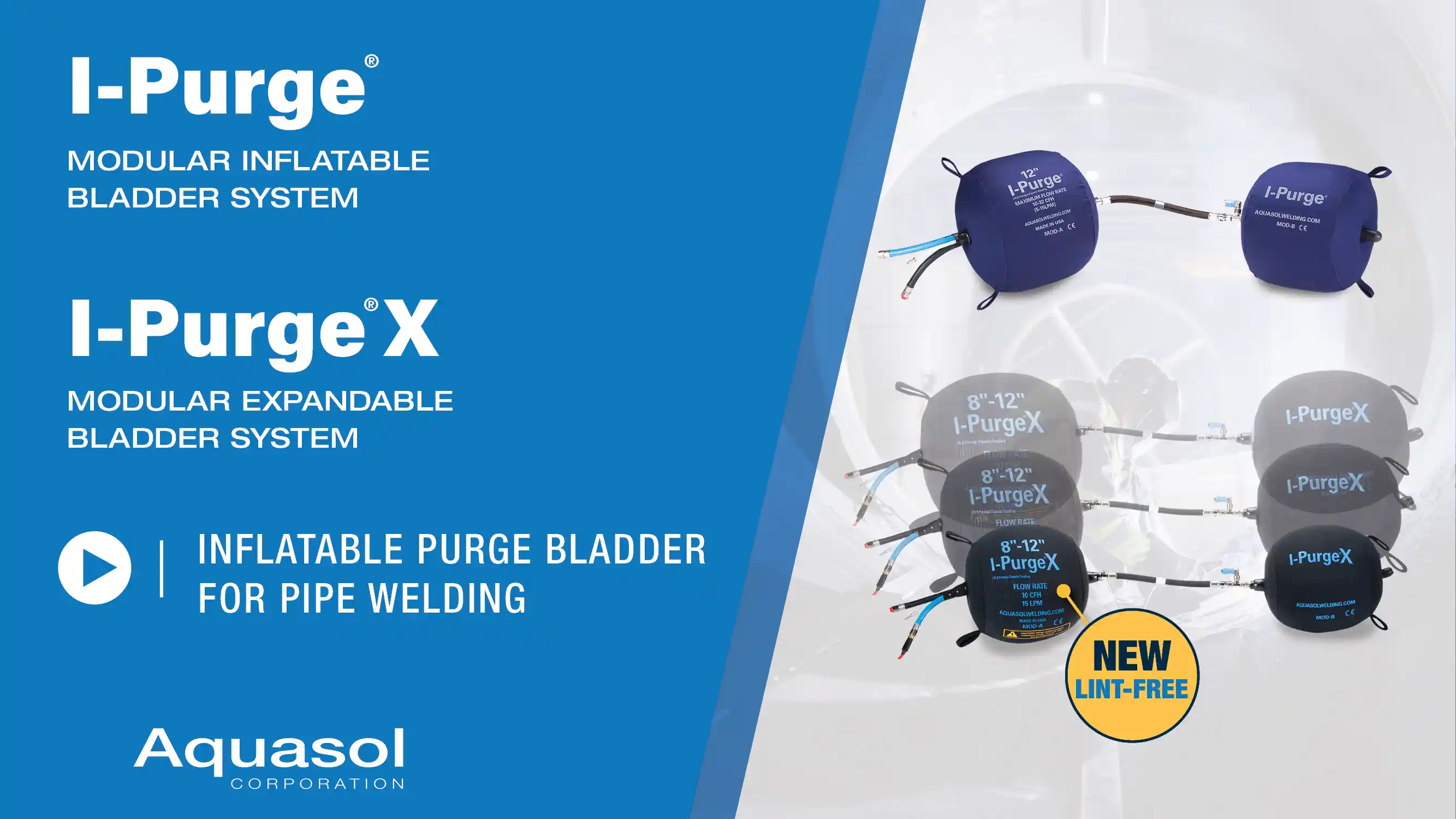
O sistema modular de bolsa expansível I-Purge® X agora conta com um inovador material NOVO que não solta fiapos, o que o torna ainda mais adequado para ambientes limpos e controlados, nos quais eliminar fiapos e partículas é fundamental.
O I-Purge® X é o sistema de bexiga inflável modular mais avançado e mais adaptável tecnologicamente até o momento.
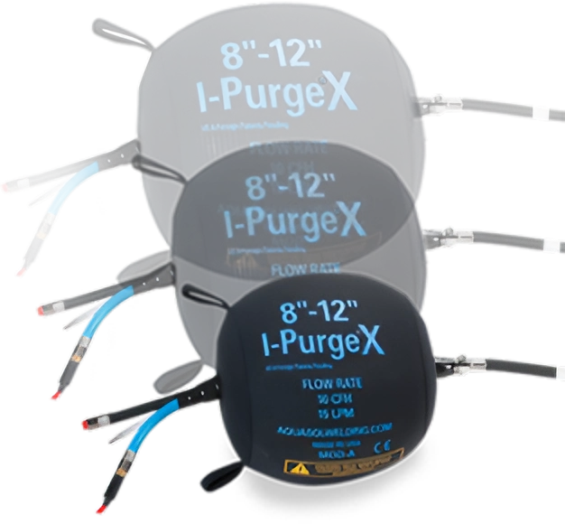
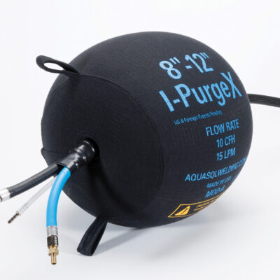
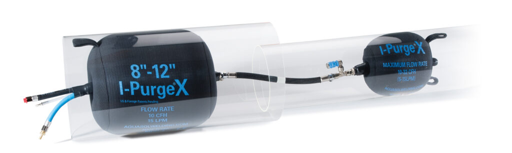
O I-Purge X vem equipado com sua revolucionária tecnologia de expansão de bexiga (BET) que permite que uma unidade se encaixe em vários tamanhos de tubos. As bexigas têm a habilidade de se expandir e de se contrair a fim de se encaixarem em cada especificação de tubo e são protegidas por uma capa externa resistente a faíscas que não derrete.
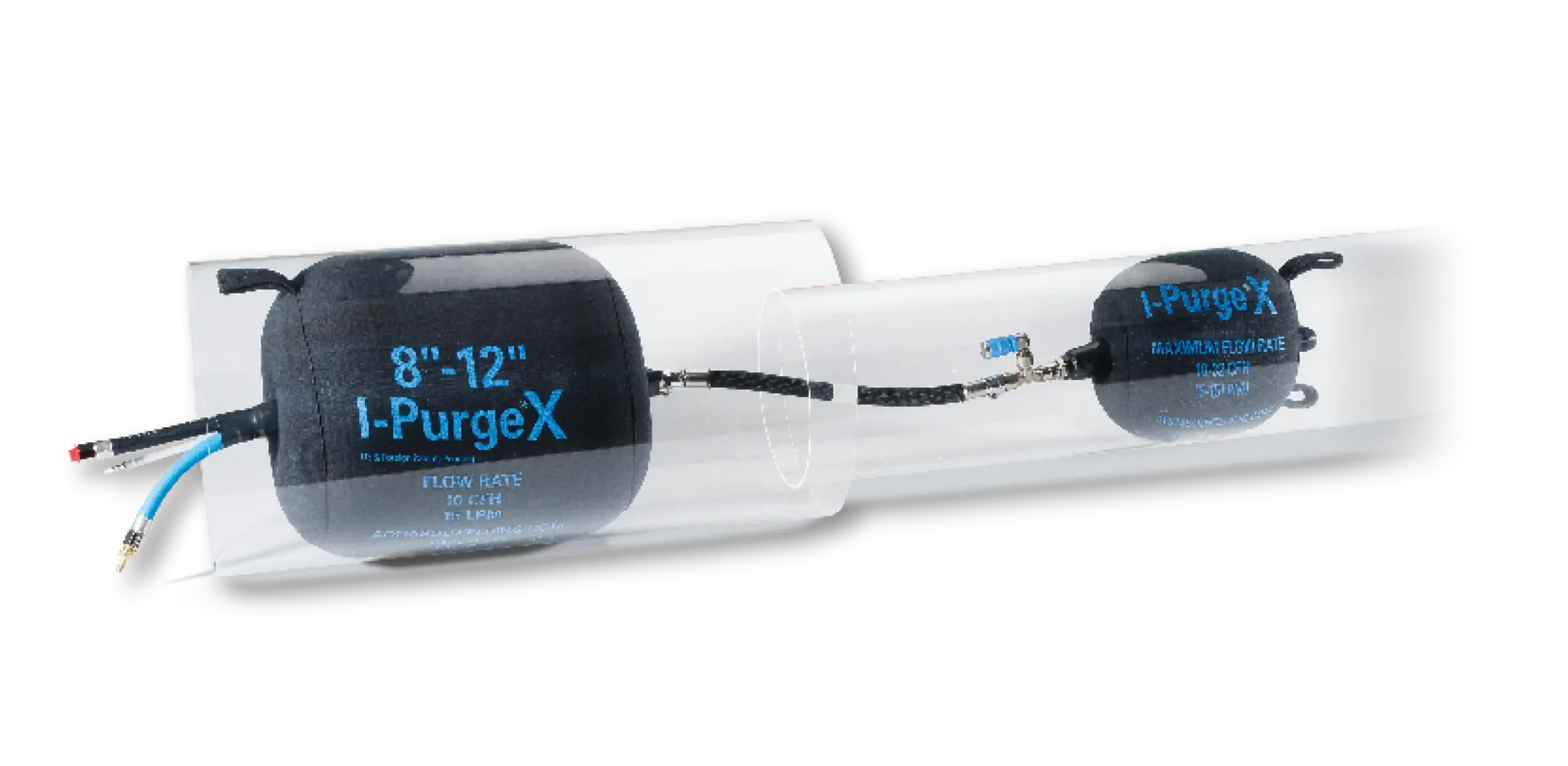
Esses recursos de última geração permitem que o operador crie diversas configurações, incluindo um tampão de tubo unilateral e um redutor.
As bexigas estão disponíveis em tamanhos de 2″-3″ (51 mm – 76 mm) a 60″-70″ (1524 mm – 1778 mm) e podem ser adquiridas individualmente ou como um sistema completo, uma vantagem clara caso sejam necessários tamanhos adicionais ou a substituição de algum componente.
Integrado com um comprimento extenso, chicote resistente ao calor intenso; o I-Purge X é a solução de purga de tubo mais versátil e é ideal para oficinas de fabricação e chãos de fábrica onde a purga é necessária. Fabricado nos EUA, a partir de produtos da mais alta qualidade, o I-Purge X é uma solução de bexiga reutilizável de longo prazo que é expansível, extensa e simplesmente extraordinária.
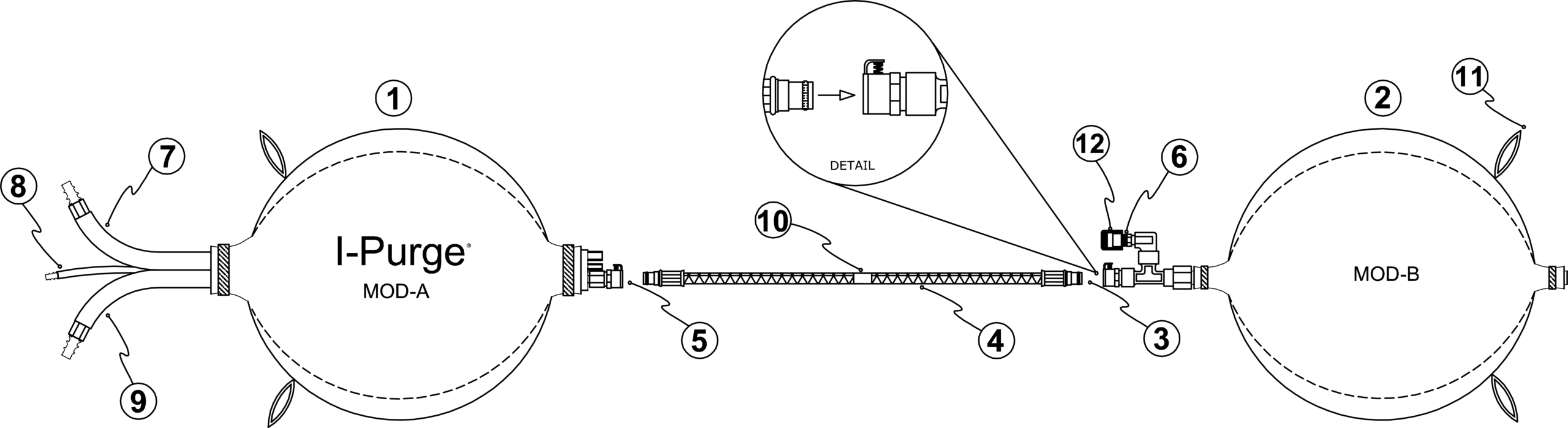
Bexigas Infláveis Módulos A e B
Chicotes Extensos de alto Calor
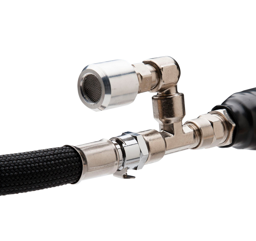
Equipamentos Permutáveis de Rápida Conexão
Válvula de Escape Exclusiva
Difusor de Gás Inerte
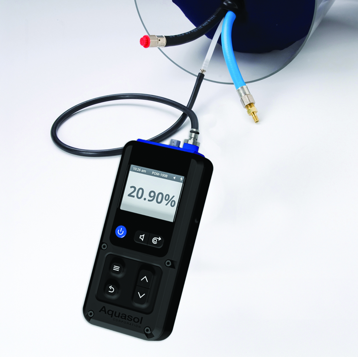
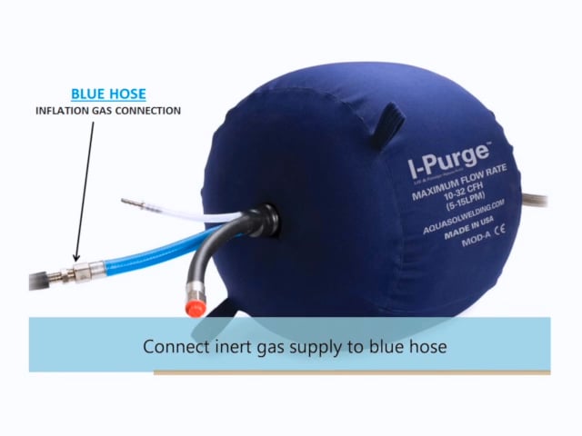
Sistema de Tubulação Interno Tri-Flow (Mangueiras Azul, Preta e Branca)
Múltiplas portas de escape/entrada para purga de solda mais eficiente e mais rápida
Conexões Separadas:
Azul – Inflação de bexigas
A função inicial é inflar bexigas e em seguida encher a zona de solda com gás nobre
Preta – Aumento do alagamento da zona de solda
Projetada para acelerar purga, a segunda mangueira de purga (PRETA) é utilizada para inundar a zona de solda com gás inerte e evacuar oxigênio sob uma taxa mais rápida; com isso permitindo o começo da soldagem
Branca – Conexão de exaustão
Conecte esta mangueira ao monitor de oxigênio, como o Pro Ox-100 da Aquasol, que obtém leituras de até 100 PPM (0.01%), para monitoramento contínuo ou local de oxigênio na zona de solda
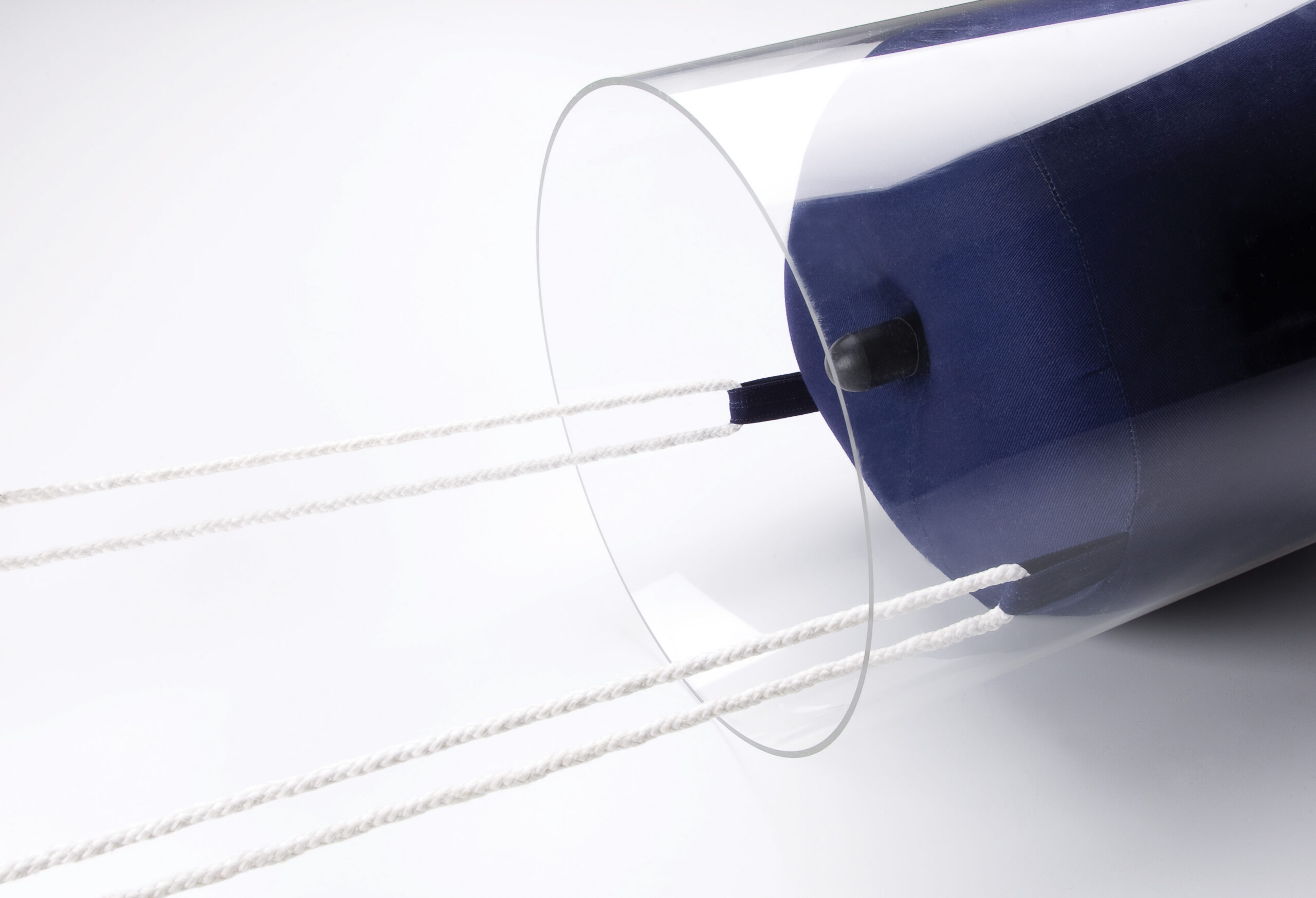
Laços para Puxar
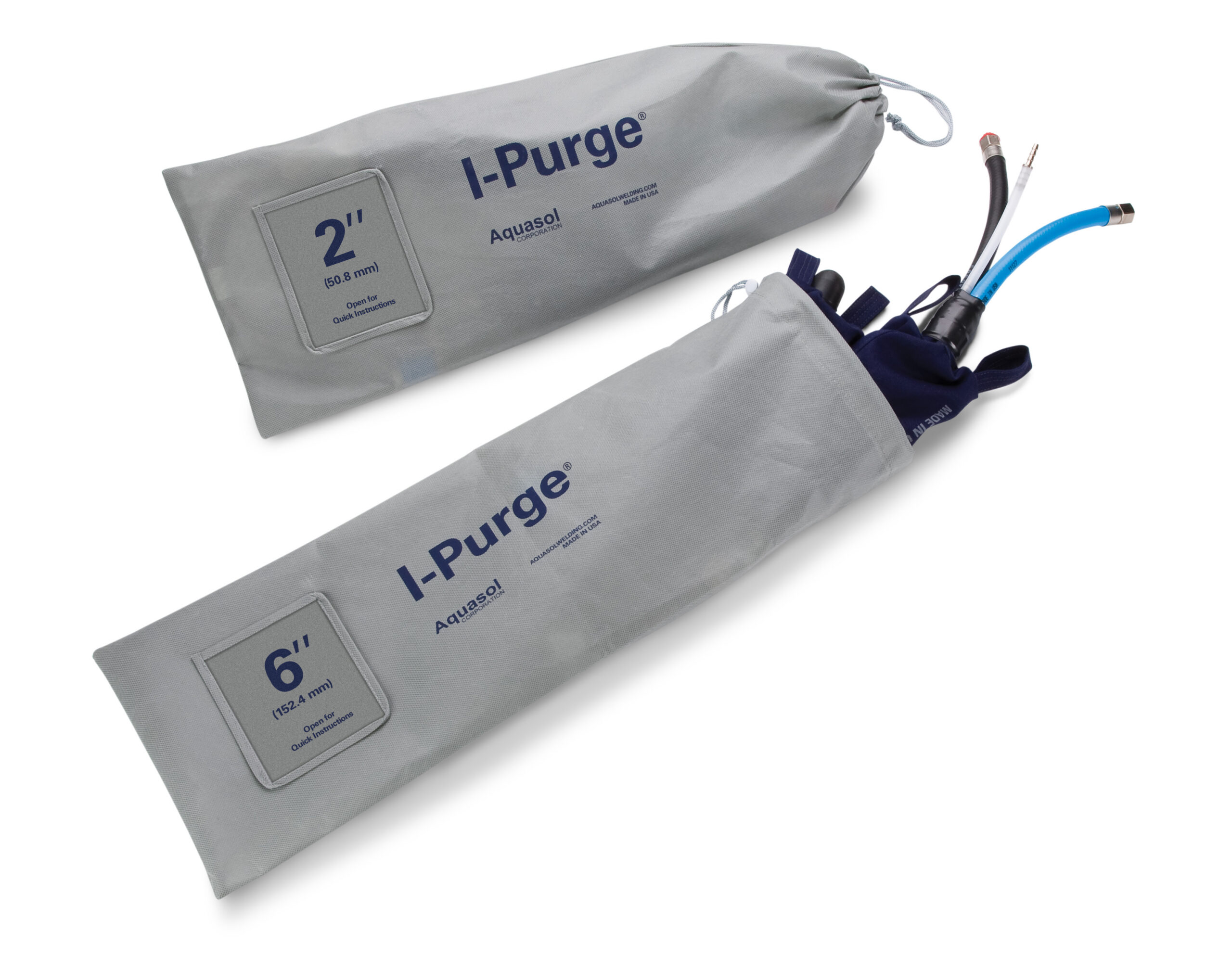
Bolsa Transportadora
Redutor I-Purge X
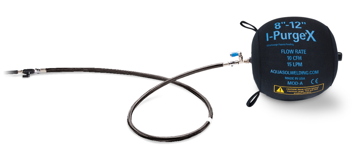
Bujão de Tubo Inflável Isolador I-Purge X e Bexiga de Purga Individual
Adaptadores de Isolamento I-Purge:
Aproveite ao máximo o nosso design modular!
Converta os seus sistemas I-Purge de duas bolsas em isoladores unilaterais para geometrias de soldadura complexas. Tanto as nossas bolsas I-Purge como as I-Purge X podem ser convertidas graças ao nosso inovador design modular.
Adaptador I-Purge Mod-A: Um difusor de ligação rápida para a sua bolsa I-Purge Mod-A.
Adaptador I-Purge Mod-B: Uma mangueira com conexões para ligar a sua bolsa I-Purge Mod-B ao seu cilindro de argónio.
Sistema Modular de Bexiga de Purga Inflável I-Purge X:
Equipado com os componentes intercambiáveis mais avançados.
Guia de Instruções Rápidas
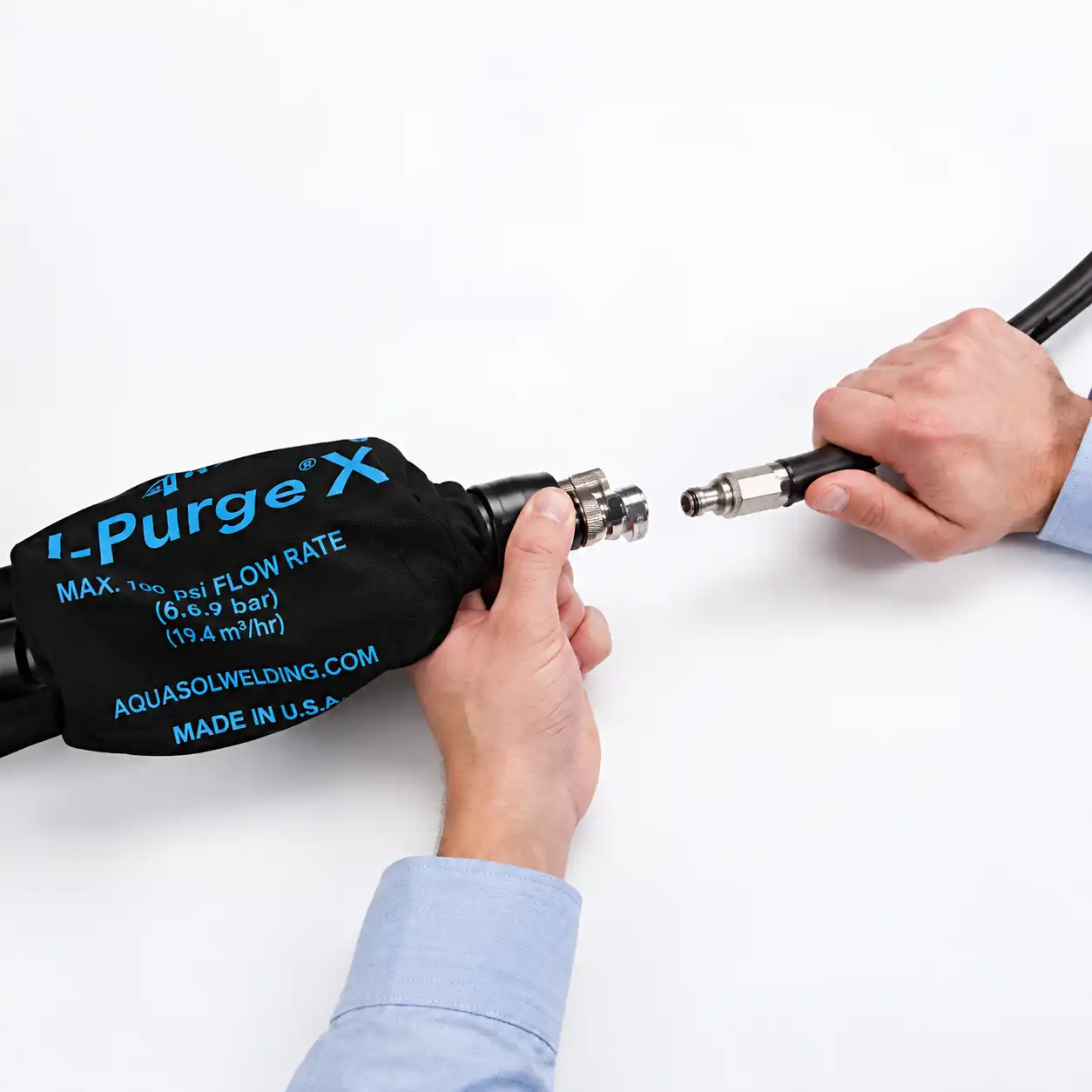
1. Garanta que I-Purge esteja completamente montado (ex. os módulos estejam conectados de forma segura ao chicote utilizando equipamentos de conexão rápida).
2. Se necessário, conecte o cabo, correia ou fio aos laços de puxar nas extremidades dos módulos da bexiga. Isto permitirá fácil inserção e remoção do sistema.
3. Conecte as linhas de gás inerte às mangueiras AZUL e PRETA. A mangueira de gás AZUL é exigida para inflar as bexigas de purga e a mangueira de gás PRETA é opcional para acelerar o processo de purga
4. Posicione a unidade de purga no tubo para alinhar o indicador luminescente com a folga original
5. Ligue o fornecimento de gás para inflar as bexigas e purgar a zona de solda
Taxas de fluxo recomendadas para purga:
A mangueira de gás AZUL deve transferir gás inerte a 32 SCFH (15 LPM) para os modelos 2″-36″, 60 SCFH (28,5 LPM) para os modelos 38″-58″ e 120 SCFH (56,6 LPM) para os modelos 60″-70″.
6. Uma vez que uma vedação estreita tenha sido atingida, comece a soldagem.
7. Sempre mantenha uma taxa de fluxo constante durante a inflação, purga e soldagem.
8. Uma vez que a solda esteja completa, desligue o fornecimento de gás para esvaziar as bexigas. Após a zona de calor resfriada completamente, remova I-Purge X do tubo. Tenha certeza de desconectar todas as linhas de gás e monitorar o equipamento.
9. Limpe I-Purge X e armazene na bolsa transportadora fornecida quando não estiver em uso.
(*Consulte o Manual do Produto da Aquasol para obter instruções detalhadas)
| ITEM NO | MINIMUM DIAMETER | MAXIMUM DIAMETER | STANDARD HARNESS LENGTH | DESCRIPTION | |||
|---|---|---|---|---|---|---|---|
| Inglês | Metric | Inglês | Metric | Inglês | Metric | ||
| XABLD 2-3 | 2″ | 51 mm | 3″ | 76 mm | 11″ | 279 mm | 2-3″ I-Purge X Expandable Double Purge Bag System with High Heat Harness |
| XABLD 4-6 | 4″ | 102 mm | 6″ | 152 mm | 11″ | 279 mm | 4-6″ I-Purge X Expandable Double Purge Bag System with High Heat Harness |
| XABLD 8-12 | 8″ | 203 mm | 12″ | 305 mm | 11″ | 279 mm | 8-12″ I-Purge X Expandable Double Purge Bag System with High Heat Harness |
| XABLD 14-18 | 14″ | 356 mm | 18″ | 457 mm | 16″ | 406 mm | 14-18″ I-Purge X Expandable Double Purge Bag System with High Heat Harness |
| XABLD 20-26 | 20″ | 509 mm | 26″ | 660 mm | 18″ | 457 mm | 20-26″ I-Purge X Expandable Double Purge Bag System with High Heat Harness |
| XABLD 28-36 | 28″ | 711 mm | 36″ | 914 mm | 20″ | 509 mm | 28-36″ I-Purge X Expandable Double Purge Bag System with High Heat Harness |
| XABLD 38-48 | 38″ | 965 mm | 48″ | 1219 mm | 36″ | 914 mm | 38-48″ I-Purge X Expandable Double Purge Bag System with High Heat Harness |
| XABLD 50-58 | 50″ | 1270 mm | 58″ | 1473 mm | 42″ | 1067 mm | 50-58″ I-Purge X Expandable Double Purge Bag System with High Heat Harness |
| XABLD 60-70 | 60″ | 1524 mm | 70″ | 1778 mm | 42″ | 1067 mm | 60-70″ I-Purge X Expandable Double Purge Bag System with High Heat Harness |
| ITEM NO | DIMENSIONS | DESCRIPTION | |
|---|---|---|---|
| English | Metric | ||
| XISO 2-3 | 2-3″ | 51-76 mm | 2-3″ I-Purge X Isolator Plug de Lado Único com Mangueira de 10′ e Válvula |
| XISO 4-6 | 4-6″ | 102-152 mm | 4-6″ I-Purge X Isolator Plug de Lado Único com Mangueira de 10′ e Válvula |
| XISO 8-12 | 8-12″ | 203-305 mm | 8-12″ I-Purge X Isolator Plug de Lado Único com Mangueira de 10′ e Válvula |
| XISO 14-18 | 14-18″ | 356-457 mm | 14-18″ I-Purge X Isolator Plug de Lado Único com Mangueira de 10′ e Válvula |
| XISO 20-26 | 20-26″ | 509-660 mm | 20-26″ I-Purge X Isolator Plug de Lado Único com Mangueira de 10′ e Válvula |
| XISO 28-36 | 28-36″ | 711-914 mm | 28-36″ I-Purge X Isolator Plug de Lado Único com Mangueira de 10′ e Válvula |
| XISO 38-48 | 38-48″ | 965-1219 mm | 38-48″ I-Purge X Isolator Plug de Lado Único com Mangueira de 10′ e Válvula |
| XISO 50-58 | 50-58″ | 1270-1473 mm | 50-58″ I-Purge X Isolator Plug de Lado Único com Mangueira de 10′ e Válvula |
| XISO 60-70 | 60-70″ | 1524-1778 mm | 60-70″ I-Purge X Isolator Plug de Lado Único com Mangueira de 10′ e Válvula |
| ITEM NO. MODULE A | ITEM NO. MODULE B | DIMENSIONS | DESCRIPTION | |
|---|---|---|---|---|
| English | Metric | |||
| XABLD-2 MOD A | XABLD-2 MOD B | 2″ | 51 mm | 2″ I-Purge X Module A or B |
| XABLD-4 MOD A | XABLD-4 MOD B | 4″ | 102 mm | 4″ I-Purge X Module A or B |
| XABLD-8 MOD A | XABLD-8 MOD B | 8″ | 203 mm | 8″ I-Purge X Module A or B |
| XABLD-14 MOD A | XABLD-14 MOD B | 14″ | 356 mm | 14″ I-Purge X Module A or B |
| XABLD-20 MOD A | XABLD-20 MOD B | 20″ | 509 mm | 20″ I-Purge X Module A or B |
| XABLD-28 MOD A | XABLD-28 MOD B | 28″ | 711 mm | 28″ I-Purge X Module A or B |
| XABLD-38 MOD A | XABLD-38 MOD B | 38″ | 965 mm | 38″ I-Purge X Module A or B |
| XABLD-50 MOD A | XABLD-58 MOD B | 50″ | 1270 mm | 50″ I-Purge X Module A or B |
| XABLD-60 MOD A | XABLD-60 MOD B | 60″ | 1524 mm | 60″ I-Purge X Module A or B |
| XABLD-70 MOD A | XABLD-70 MOD B | 70″ | 1778 mm | 70″ I-Purge X Module A or B |
| ITEM NO | DIMENSIONS | DESCRIPTION | |
|---|---|---|---|
| English | Metric | ||
| ABLD-ELH-24 | 24″ | 610 mm | 24″ (2′) Extended Length High Heat Harness |
| ABLD-ELH-36 | 36″ | 914 mm | 36″ (3′) Extended Length High Heat Harness |
| ABLD-ELH-48 | 48″ | 1219 mm | 48″ (4′) Extended Length High Heat Harness |
| ABLD-ELH-72 | 72″ | 1828 mm | 72″ (6′) Extended Length High Heat Harness |
| ABLD-ELH-CUSTOM | Any Size | Any Size | Custom Lengths Available Upon Request |
| ABLD-CNADP | N/A | N/A | 1/4″ Female MPT to 1/4 Female BSPP Conversion |
One I-Purge X unit can expand to fit multiple pipe sizes, and all pipe schedules that correspond with a pipe’s diameter. An 8″ to 12″ I-Purge X can fit any pipe sizes in between this range. The range of sizes is displayed on Module A of the system. Although I-Purge X is expandable, it is important not to overinflate the bladders as they can burst, causing damage to the unit.
No tools are required when configuring the system. To assemble or disassemble the modules from the harness, simply press on the quick connect fitting at the end of each side of the harness and remove or connect.
The bridge harness is the connecting hose between the two inflatable bladders. It is comprised of a flexible braided fiberglass shielding over a high-heat resistant inner tube.
The central point of the bridge harness is marked with a luminescent indicator to easily align the center of the unit with the root gap. It is important to position the bladders equal distances from the weld joint to prevent over heating of one side, which could rupture or damage the bladder.
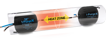
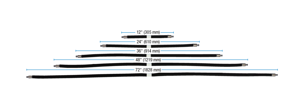
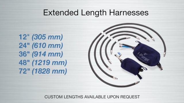
Extended length harnesses offer flexibility to extend placement of the inflatable bladders outside the heat affected zone (HAZ) and to accommodate pre-heating (high-heat) welding applications. Extended length harnesses are available in standard sizes including 12″ (305 mm), 24″ (610 mm), 36″ (914 mm), 48″ (1219 mm) and 72″ (1828 mm). I-PurgeX sizes 36″ and greater are equipped with a high flow harness to expedite inflation. Custom lengths are available upon request.
To prevent exposure to the HAZ, use an extended length harness appropriate for the situation. These harnesses are sold separately and are available in many custom lengths.
I-Purge X CAN be used in a pre-heated pipe. For pre-heating and high-heat applications, select an appropriate size of an extended length harness to ensure placement outside of the heat-affected zone (HAZ).
The outer covering on the inflatable bags of I-Purge X is the only component which should come into direct contact with the pipe. This material is infused with spark resistant elements which prevent it from catching fire when exposed to sparks and exceedingly hot objects. The outside material of the bladders can withstand temperatures as high as 400°F (205°C). Since the inside of the bladder has a lower heat resistance, it is advisable not to exceed a temperature of 250°F (120°C) for proper operation of the entire system.
I-Purge X can accommodate higher temperatures (such as those in pre-heating welding) applications by attaching an extended length bridge harness purchased separately.
I-Purge X offers the flexibility of combining modules of different sizes to create a unique configuration. For example, a 4-6″ (102 mm to 152 mm) module A can be connected to a 8-12″ (203 mm to 305 mm) module B.
If you believe the bladders were overinflated during operation, terminate gas flow immediately. When the bladders do not hold air, they may have been overinflated, causing them to burst. This can be prevented by adhering to the flow rates listed in the manual. Aquasol does not warrant any overinflation system failures. For more details, review Warranty and System Operation sections of the manual.
I-Purge X and I-Purge (standard) components CANNOT be interchanged. The calibration of the relief valve on I-Purge X is different from the standard I-Purge.
During some applications, the bladder component of the isolator may not be visible, therefore all I-Purge X Isolator units are equipped with a pressure relief valve to prevent over inflation of the unit. Therefore, a constant supply of gas must be maintained to keep a tight seal on the pipe wall (Refer to Isolator – System Operation).